Section 1: Programming the CNC
Understanding G-Code
All CNC’s are controlled by G-Code, which are the set of discrete instructions that control all elements of the machine. According to Wikipedia:
Quote
“G-code instructions are provided to a machine controller (industrial computer) that tells the motors where to move, how fast to move, and what path to follow. The two most common situations are that, within a machine tool such as a lathe or mill, a cutting tool is moved according to these instructions through a toolpath cutting away material to leave only the finished workpiece and/or an unfinished workpiece is precisely positioned in any of up to nine axes[1] around the three dimensions relative to a toolpath and, either or both can move relative to each other. The same concept also extends to noncutting tools such as forming or burnishing tools, photoplotting, additive methods such as 3D printing, and measuring instruments.”
Wikipedia
Your job as a CNC programmer is to create the G-code to make the parts that you want. In other words, by giving the computer a set of instructions, you can replicate the same part over and over again.
This is an example of a G-Code program
(DRILL1)
(T1  D=4.762 CR=0. TAPER=118DEG - ZMIN=-6.35 - DRILL)
G90 G94 G91.1 G40 G49 G17
G21
G53 G0 Z0.

(DRILL1)
M5
T1 M6
S5000 M3
G54
M8
G0 X11.906 Y-20.622
G43 Z15. H1
Z5.
G98 G81 X11.906 Y-20.622 Z-6.35 R5. F254.
X-11.906
Y20.622
X11.906
G80
Z15.

M9
G53 G0 Z0.
G53 G0 X0. Y0.
M30

The image shows what the program actually does. In this case, it drills out 4 holes. In the past, G-code was manually written, which meant every line was typed out, instead of being automatically generated. This required extensive knowledge of the G-code language and only rudimentary operations could be feasible done. Thankfully with CAM software, we no longer need to manually write all the G-code. A computer science analogy would be to think of manually coding as a low level computer language, such as assembly, whereas CAM is Python or Java. 3045 uses Fusion 360, as our primary CAM software, since it’s free and has a plethora of features.
Introduction to Fusion 360 CAM
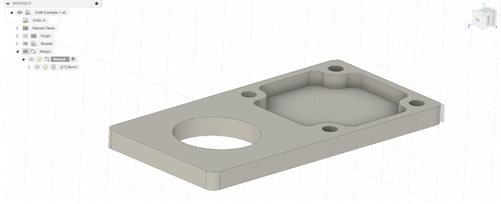
(link to Fusion 360 student license) Before we can CAM our tool paths, we first need a 3d model of our desired part. This will be designed in Computer Aided Design (CAD) beforehand. We then import the model in fusion 360. Use control+o and then select “open from my computer…” to import a local file.

Next open CAM example 1. Fusion 360 has different workspaces. By default we are in the design workspace but there are also simulation, render, animation, drawing, and manufacture workspaces. The manufacture workspace contains the CAM along with a few other useful features.
Creating a Setup
Now that we have the model, we need to define a few parameters before we can begin creating tools paths. There are several parameters that may be set during the set up, but the most important ones to keep in mind are defining the model, stock, axis orientation, and origin (also known as the work coordinate offset or zero position). In other words, we define what we are the part out of, what up and down and side to side is relative to the part. The origin will be critical in defining where your part is relative to the machine.
First switch to the manufacture workspace on the top left. Note: Make sure your units are set in inches instead of millimeters (Google this if you don’t know how to change your units in fusion).

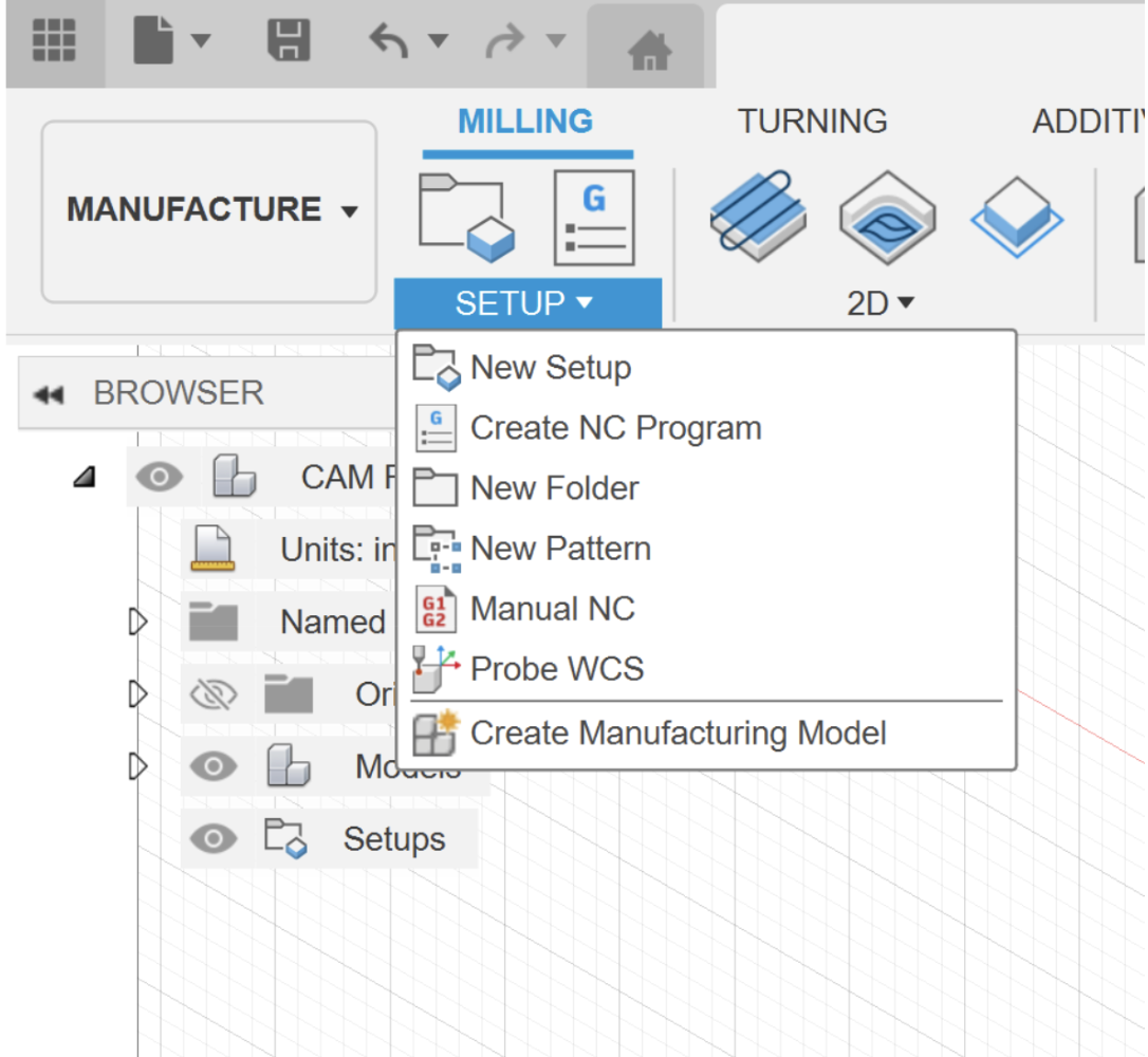
Next create a new setup.
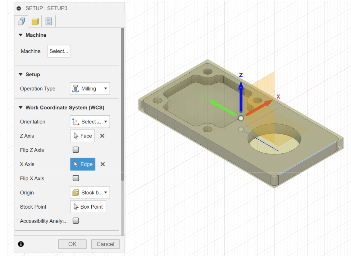
Edit the Work Coordinate System orientation until you have the X, Y, Z pointing in this direction.
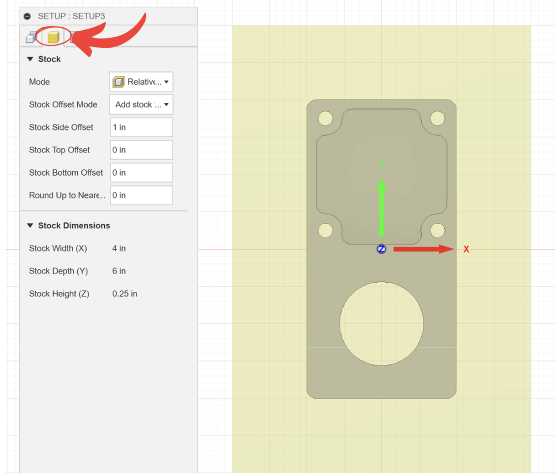
Click on the stock tab and copy these settings.
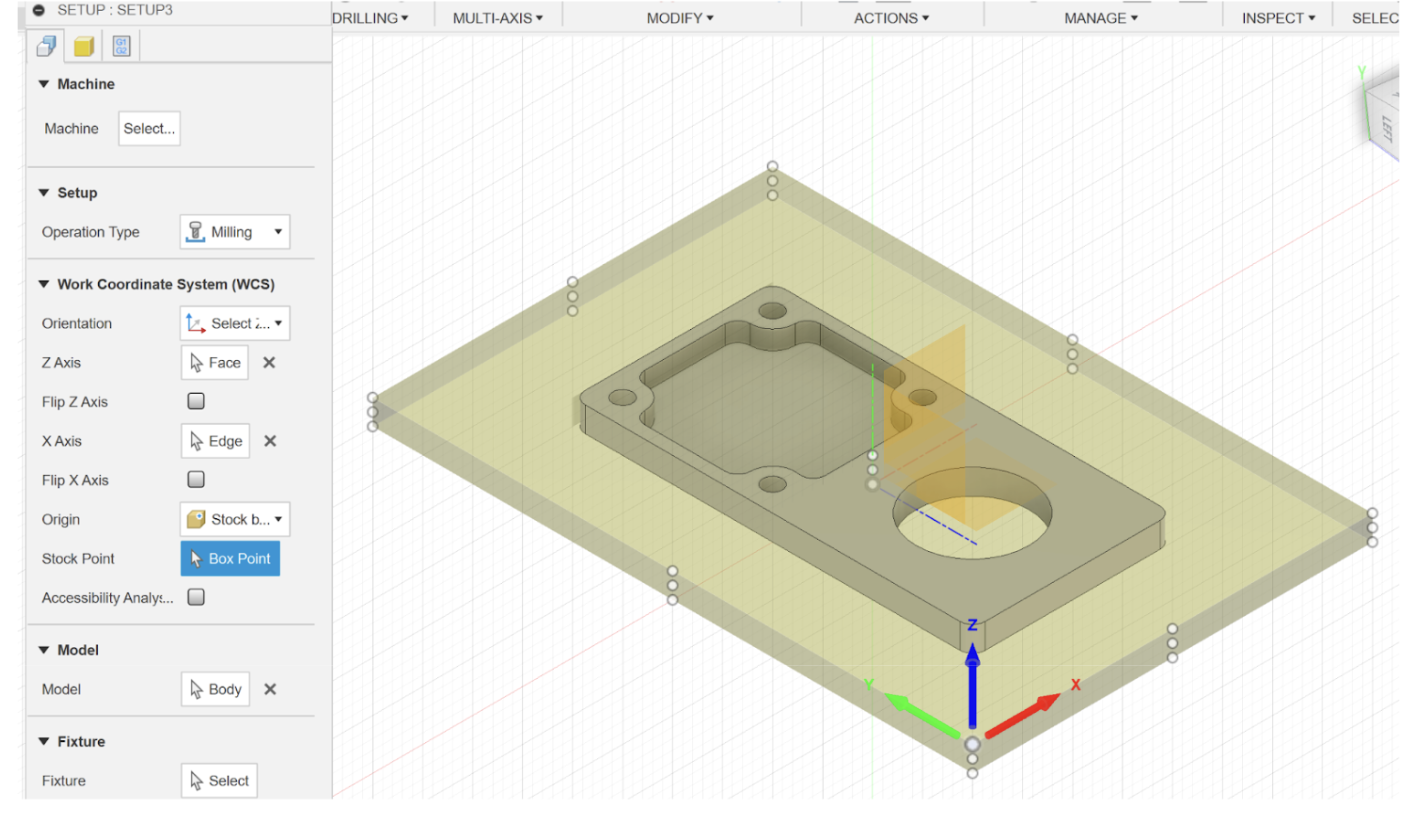
Go back to the setup tab and set the origin to Stock box point and select the following point. Finish the set up by clicking OK at the bottom or pressing enter.
Generating Toolpaths

A tool path is exactly what it sounds like, it’s the path the tool takes. Notice how since we are in the manufacture workspace, our toolbar has been completely replaced with new “features”. Toolpaths are controlled by strategies, which are what features are called in CAM. Just like how your CAD model is controlled by features such as extrude, filet, and hole, your toolpath is controlled by strategies such as adaptive clearing, contour, and bore. Strategies may also be called operations. For Milling operations, these strategies are divided into two categories, 2D and 3D. In our case, we will exclusively use 2D. Of the 2d strategies, we stick to just 4 operations: Adaptive clearing, pocket, contour, and bore.
Strategy |
Quality |
Description |
Use Case |
|---|---|---|---|
Adaptive Clearing |
Rough |
Optimizes tool load by removing sharp turns. Used to remove large amounts of material but leaves uneven and poor finish. |
Used for initial rough cuts |
Finish |
Constantly loads the tool by following parallel contours. It can be used to remove chunks of material but is typically used after adaptive clearing as a finishing strategy. |
Used for creating pockets in parts |
|
Contour |
Finish |
Follows the contour of the part. Used to finish side walls left by adaptive clearing. It is also used with step downs to cut a part out of stock. |
Used for finishing edges |
Bore |
Finish |
Creates a helical to interpolate a hole from a smaller diameter end mill. Typically used for smaller holes such as screw holes, or a finish operation for big holes. |
Used for drilling operations |
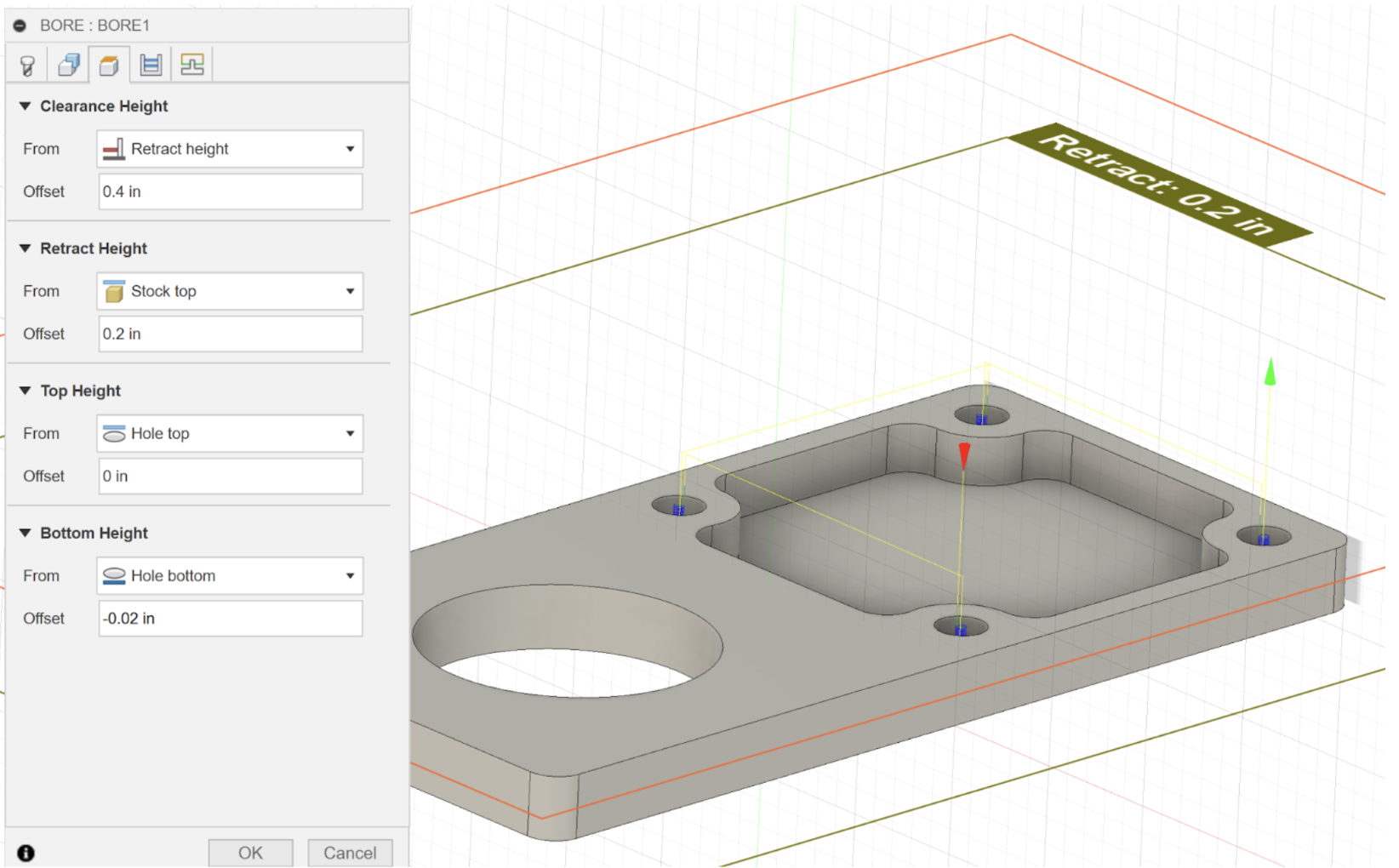
Programming your first strategy may seem daunting at first. However, all strategies more or less share the same parameter. Once you understand what each parameter means, they can be applied universally to almost all strategies. There can be up to 6 tabs when creating strategy, with some strategies omitting certain strategies. In order of the example image these are the tool, geometry, clearance heights, passes (also called cycle for drilling operations), machining type, and linking.

Generally, the first strategy on sheet metal stock will always be the 2d bore operation. This is so that we can screw down the stock to the wasteboard before continuing with the program. Select the bore operation from the toolbar.
The first tab will ask for a tool. Typically it will use the tool from the last operation but since this is the first operation, we must select a tool. Since we don’t have a tool library yet, we must select a tool from the Fusion Library or create our own. Click the blue plus to create a new tool.

Click Flat End mill and copy the following values.
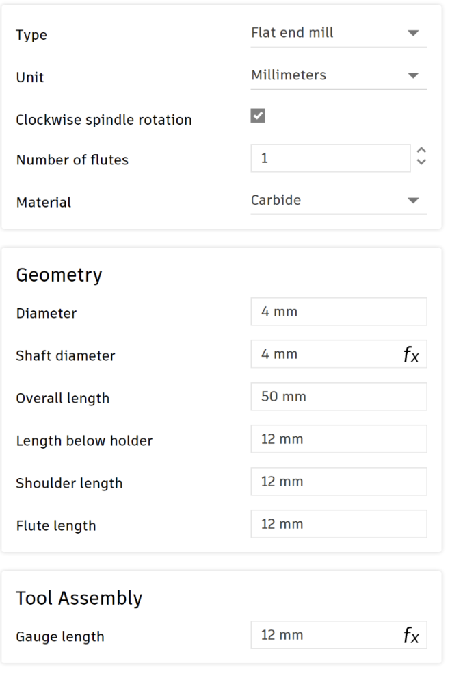
Switch the Unit from millimeters to inches. Go to the Cutting Data tab copy these settings. Only boxes without fx need to be changed.
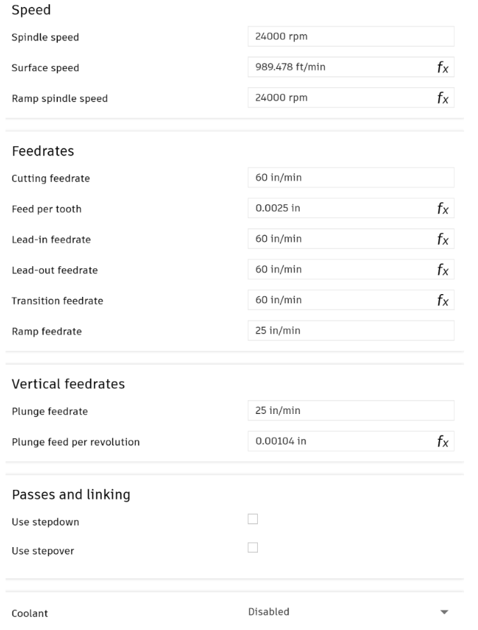
You can switch the units back to millimeters in the cutter tab. Click accept to confirm the tool. Make sure Coolant is disabled, otherwise the program won’t post.
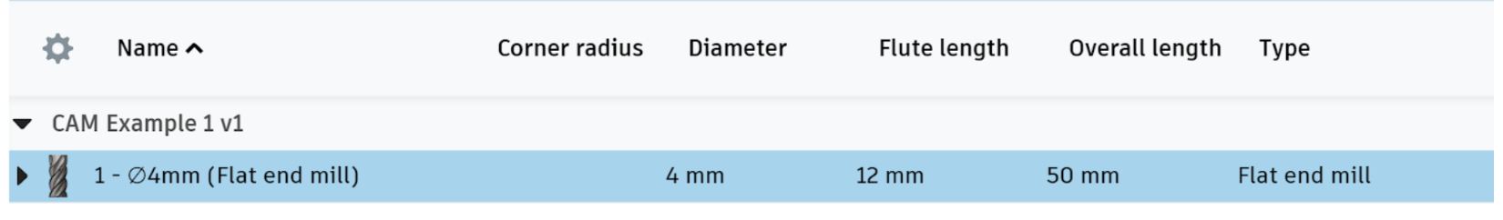
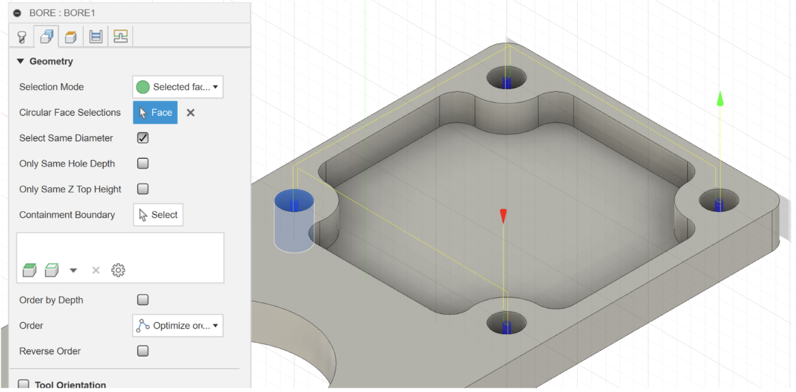
You should now have a 4mm end mill saved only in this document. Select the tool for the operation. Click one of the faces of a hole and check Select Same Diameter to select the rest.
Switch to the heights tab. We want the cutter to go slightly below the bottom of the hole in order to guarantee that the endmill has completely broken through. As a general rule of thumb, add an offset of 20 thou (-0.02”).
The rest of the default values are fine, so hit OK to finish the operation.
Your strategy should now appear under your setup. The green check means operation generated without any errors or warnings. Let’s now make the cross shaped pocket in the stock.
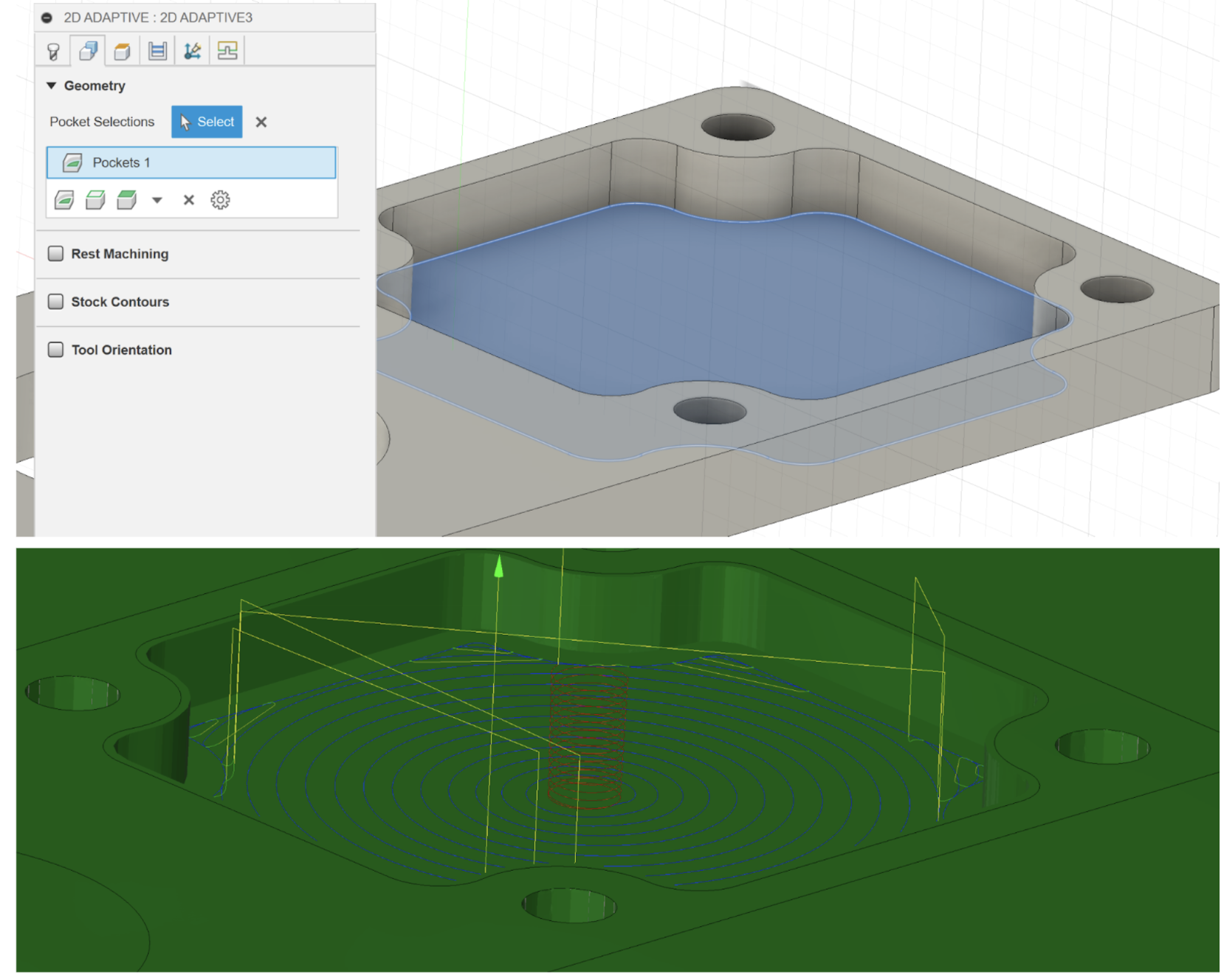
Select 2d adaptive clearing. The tool should be remembered, so move on to the next tab. Select the face of the pocket. The rest of the settings are fine, but let’s take a look at the passes tab. Notice how the stock is checked by default, this means that it will leave 20 thou of stock. This small amount of material will be removed with the finishing operation. Click OK.
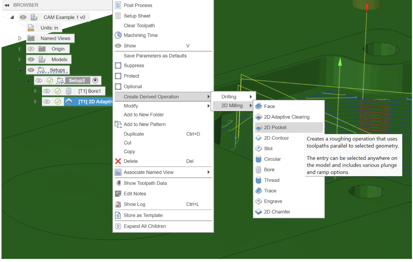
Let’s clean this up with a pocket strategy. This time, instead of creating the strategy from the toolbar, right click the 2d adaptive operation and click “Create Derive Operation” from the drop down menu. This automatically applies the same geometry selections to the next strategy. This can be useful if you have a lot of shared selected geometry between two strategies. Derive a 2D Pocket.
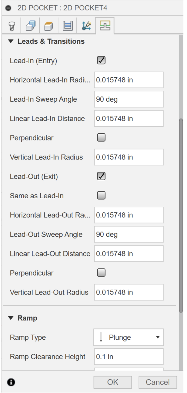
Unselect stock to leave in the passes tab. Then click on the linking tab. Leave all values default except uncheck “Same as Lead-In”, and change the Ramp Type to plunge, since we are only cutting 20 thou.
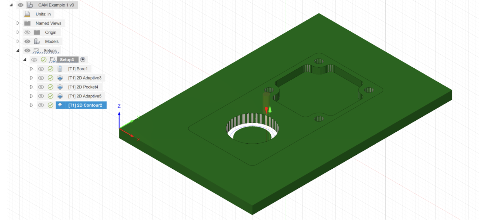
Lastly, for the bearing hole to create an adaptive clearing operation, select the bottom edge of the hole. Then derive a 2d contour operation, and keep all values as default, except for a 20 thou break through on the heights tab.
Here is what it should look like.
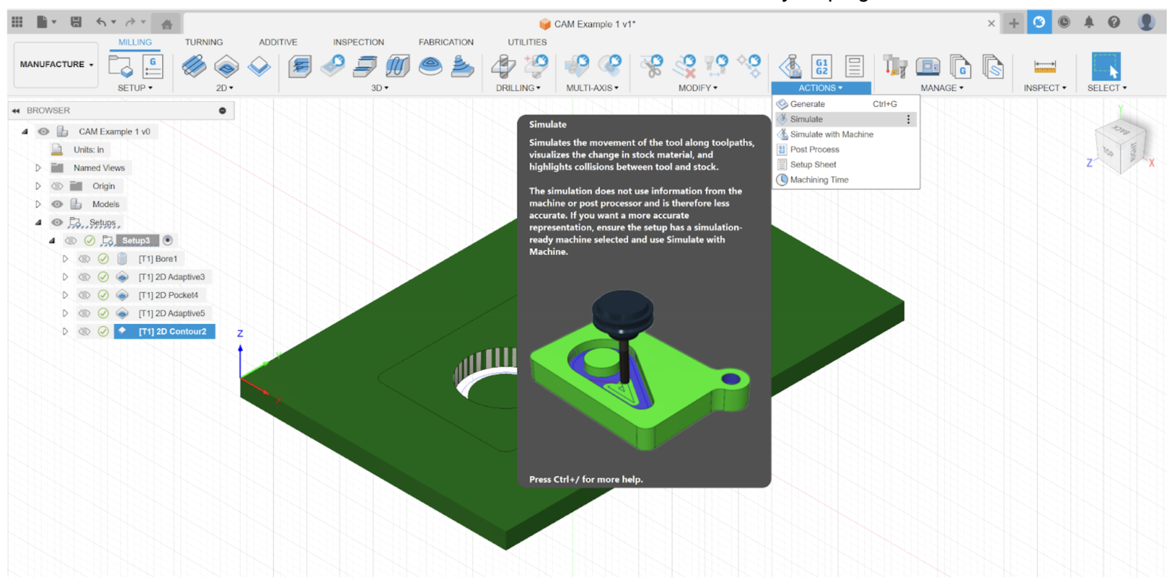
You can also use the simulate feature under the Action tab to watch an animation of your program.
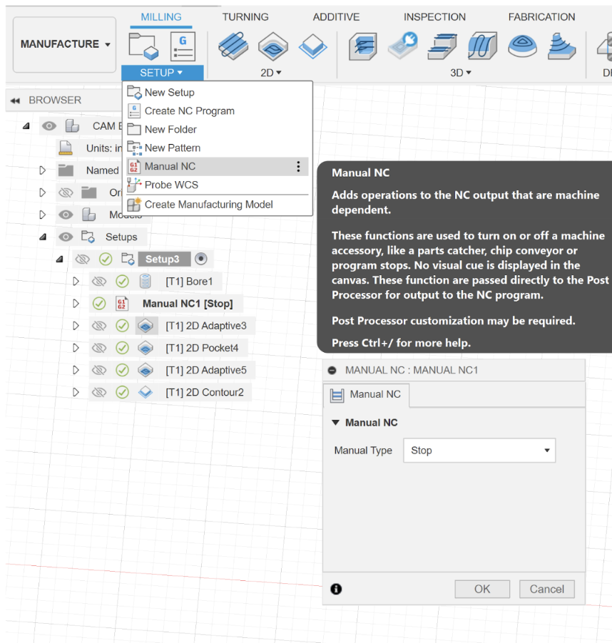
Before we post this program, we want to add a stop in the program so we can add screws to hold the part down. Under SETUP select Manual NC and choose stop. Then drag the operation under the bore.
Posting the G-Code
Let’s recall the software analogy from earlier. Although high level languages allow us to easily conceptualize our software, they still need to be translated to extremely low level inputs known as machine language, which are ones and zeros. To do this, computers use something called a compiler. A Post-Processor is no different. In this case our high level language is our tool path and the low level machine language is G-code. A post processor allows us to export our tool path as a .tap file which we can then run off the CNC controller, Mach3Mill.
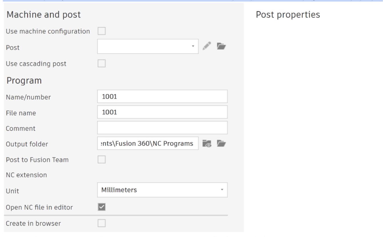
In order to post your code, click on actions on the toolbar and post process. This page should pop up:
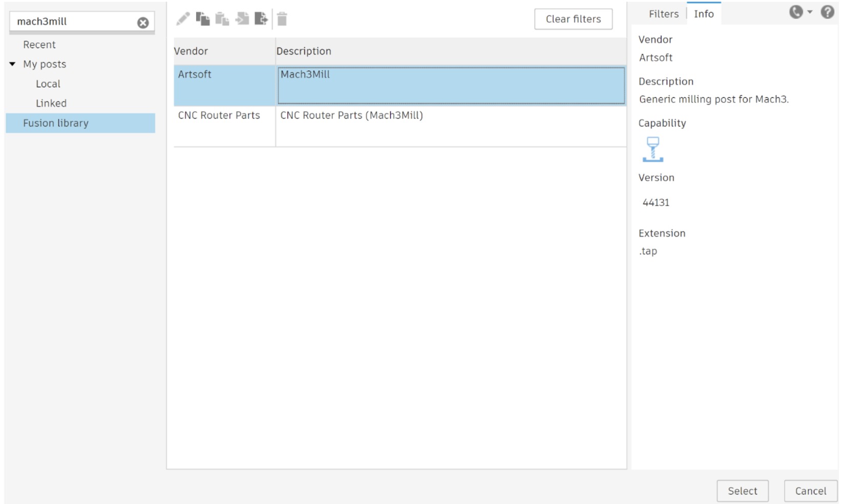
You will first need to specify your post. While all modern CNCs use G-Code each controller may have nuances on how it is interpreted. Therefore we need to specify that our CNC controller is Mach3Mill. Click the file icon to the right of the Post drop down. A second pop up should appear. On the left hand side click Fusion Library. Then on the search bar at the top left side type Mach3Mill.
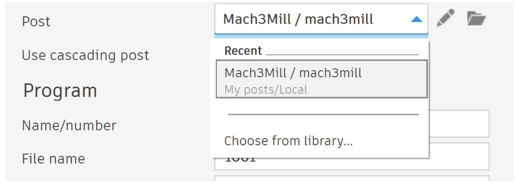
Click select and save the post processor locally. You should now see this in the post drop down:
Next I change the unit to Millimeters. The CNC controller by default is in millimeters so this will minimize confusion between the program and CNC. I’d also recommend changing your output folder to a desktop folder by clicking on the folder icon to the right of “Output Folder”. You can also uncheck “Open NC file in editor”.
We can now change the post properties on the right. I leave everything as is, but change safe retracts to G53. This means the machine will go to absolute z0 at the beginning and end of the program. Rename your program to something like “CAM example v1”.
Find your .tap file. Right click on the file and choose open with notepad. Use the scroll bar and drag it to get to the end of the program. Delete the following line: G53 G0 X0 Y0
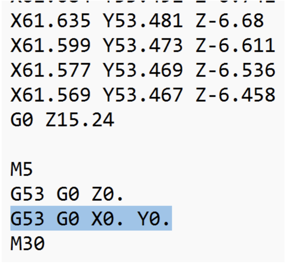
This moves the CNC all the way to absolute zero after the program which is a waste of time. You should also make other edits here such as changing the program offset. Personally I change G53 G0 Z0 to G53 G0 Z-5 at the top of the program to ensure the CNC doesn’t hit the Z axis limit switch. Remember to save any changes in the notes app, before exporting the file to the CNC.